When designing a real time system either as a loop or a bunch of tasks you must be aware of the operating timing. Each of the peripherals in the system takes a some time to complete their operations. If the peripheral is interrupt driven there is operation setup time, interrupt handling time, and post processing time to account. For polled operations there is setup time, elapsed operation time and post processing time.
Below are some timing diagrams for various peripherals. The timing diagrams show the wall clock time for the operation. They do not include any setup time or post processing time.
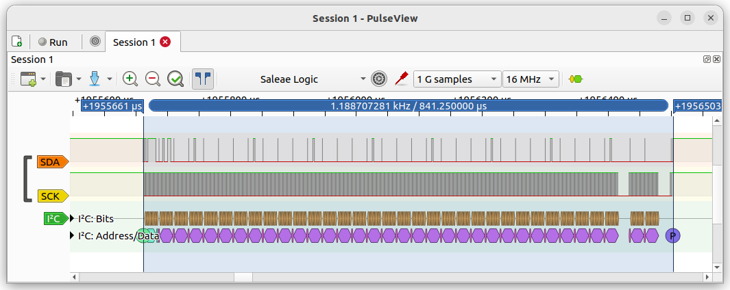
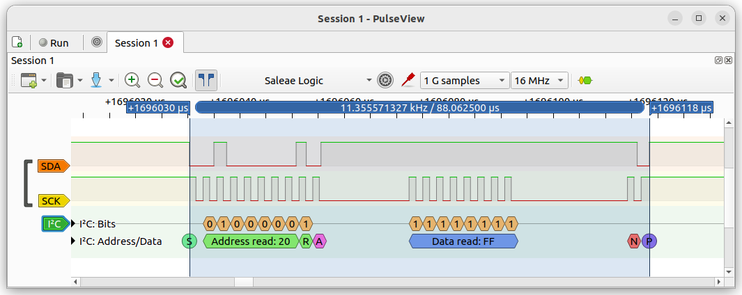
The Freenove 4WD Car uses the PCA9685 LED controller at I2C address 0x5f to drive the motors and servos. Below is the timing diagram when writing to the 4 motors.
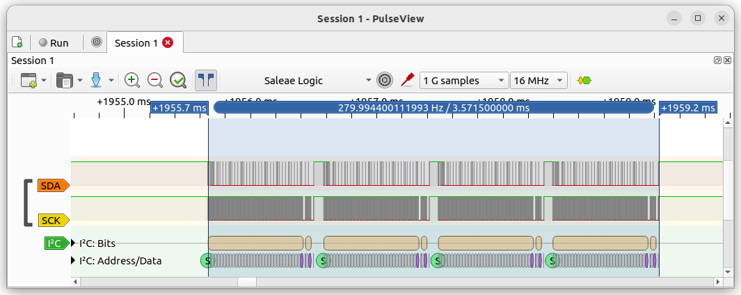
Below is the timing diagram when writing to a single servo.
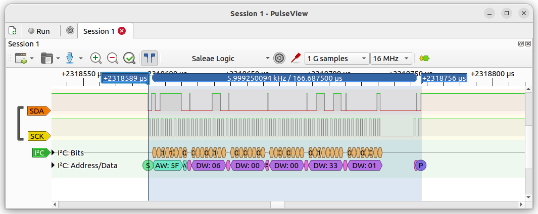
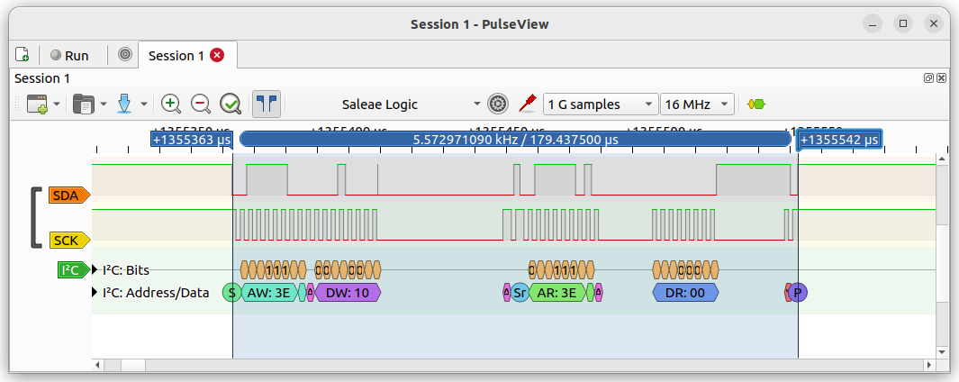
The Freenove 4WD Car uses the PCF8574 GPIO Expander at I2C address 0x20 to read the line sensors. Below is the timing diagram when reading the line sensors.
The SparkFun Line Follower Array (SEN-13582) includes an SX1509 GPIO Expander to read the values of the line sensors. The timing of the read operation is shown below.
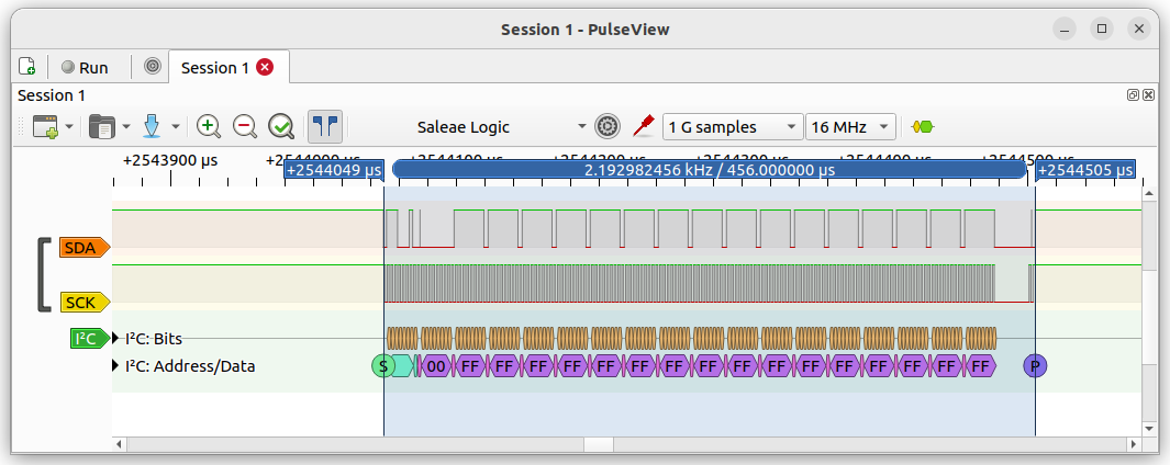
The Freenove 4WD Car uses the VK16K33 LED controller to drive the LED matrix. The timing of the write operation to turn on all LEDs is shown below.
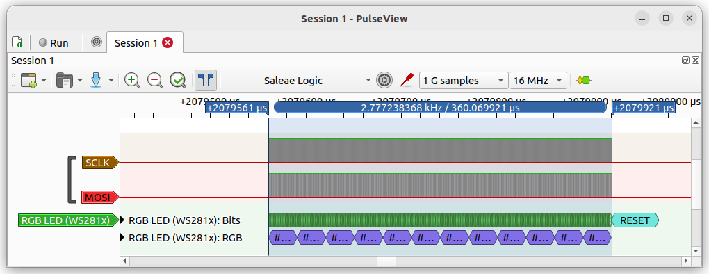
The Freenove 4WD Car has 12 WS2812 RGB LEDs, six on the front of the car and 6 on the back of the car. The timing of the write operation to change the color of all 12 LEDs is shown below.